
Index of resources |
Resources |
||
This page provides information on the equipment and resources required to carry out experiments described on this site. One of the aims of the research is to create an inanimate detector that is able to detect spin torsion radiation. Although a lot is known about the radiation itself, this has not yet been achieved and so it is necessary to carry out the experiments using dowsing detector rods. Not everyone is able to obtain any response from detector rods and another research aim is to understand why this is so. Before attempting to carry out any experiments it is necessary to make some rods and carry out some simple tests to see if responses can be obtained.
Making detector rods
Rods made from most materials have been shown to work but to avoid unnecessary problem in carrying out the experiments described on this web site it is suggested that the rods be made of copper with a diameters of 2 to 3.5mm. You should be able to get copper rod from somewhere like ebay. Note. There is little point in making the rods with very long “long” ends and pointing those ends forward in the belief that the sensitivity will be increased. What appears to happen is that the response is much more sluggish, probably due to increased inertia. In a similar vein, using a larger diameter handle of wood
or metal tube with the rod end mounted inside, perhaps using bearings,
does not appear to offer any improvement. The rods will swing very readily due to lack of any damping and will tend to give spurious results. Holding detector rods
Using and testing detector rods
The radiation that you are attempting to detect has a 21.1cm wavelength and to maximise sensitivity the rods need to be spaced at an odd number of half wavelengths. What this means in practice is that you should hold them approxmately 30cm apart. Try to avoid holding them 20cm apart as this may stop them working. Any rings on fingers should be removed as should belts and necklaces as these can affect the results. Now place a piece of metal, steel or copper and say 30cm long or more, crossways on the floor. A short section of 15mm diameter copper water pipe purchased from a DIY shop is ideal for this. Walk slowly forward holding the rods not too tightly so that they are nicely balanced. Walk over the metal and see if the rods rotate inward. It will often be necessary to walk past the metal several times before a response builds up so don’t give up if nothing happens at the first pass. When you are doing this try to keep your mind blank to avoid any reaction due to expectation. If still nothing happens try again on a different day. If the rods swing together as you pass over the metal bar then you should be able to carry out some of our experiments. Before doing so you should practice a little to get the feel of the rods.
Building a standard interferometerAn interferometer
is so called because it relies on a system of two elements that create a series of equally
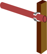
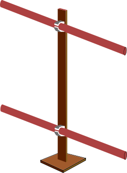
spaced interference fringes. The one used in many experiments is made with standard tube spacing of 60cm so that experimental results from various investigators in different locations can be compared. There are two types of interferometer that we use, the first type is similar to the ones that were originally used and comprises two copper pipes each 1m long spaced apart 60cm by two wooden supports. The second is now recommended and used two copper tubes and a central wooden support. This type is more versatile, the tube spacing is simple to change and it does not suffer from any interaction between the supports. The length of the interfeometer tubes is recommended to be an odd number of half wavelengths of 21.1cm and it is suggested that a length of 52.75cm be used. The tube spacing should initially be set at 60cm
Four pipe clips. - If required. These are standard pipe clips manufactured for plumbing purposes. The clips may be made of plastic and should be of a size appropriate to holding the copper tube in place.
Assembly. The two lengths of copper tube should be mounted parallel to one another and spaced 60mm apart using the two lengths of wood as supports. Either glue the ends of the pipe into holes drilled through the wood as in the diagram above or use the pipe clips to attach the tubes to the wood as shown in the diagram on the left. The centre support interferometer This interferometer has a central softwood support approximately 1cm x 2cm x 72cm. The support is mounted on a base of 14cm x 13cm x 2cm. None of these dimensions are critical Two 52.75cm long copper tubes spaced 60cm apart are mounted on the central support using plastic pipe clips fastened to the support by steel M3 machine screws and nuts. Polyethylene film or sheet can act as a polariser for spin torsion radiation and can be used to construct screening material. Often sold as Polythene sheet it comes in a variety of forms from kitchen cling film to the sheet that builders use. The polyethylene sheet that is used in the experiments described on this website needs to be anisotropic, that is, it needs to have a molecular structure that is stretched more in one direction than another. Because of the way in which it is manufactured, most (but not all) polyethylene sheet is anisotropic. The material can be obtained from DIY stores and builders merchants in addition to being available on the internet. It is usually available in either clear or black forms, either will do. 500 gauge sheet (0.125mm thick) is recommended but cling film has also been used. Polyethylene film that has been stretched in one direction during its manufacture is referred to here as polyethylene spin polarising material Determining the stretch direction When polyethylene sheet is used, its stretch direction needs to be known. The stretch direction can often be determined by stretch marks on the surface of the film. Thicker film is sometimes cut off large rolls with the stretch direction being lengthwise. If that is the case it is normally folded width-wise with the fold marks running down its length and indicating its stretch direction. Testing for the stretch direction If the stretch direction is not clear then it can found as below. The test method is to heat the sheet to a temperature at which it shrinks to its original form. A 10cm x 10cm sheet can shrink to 10 x 3 cm for example. Cut a square sample of the polyethylene sheet material to be tested. The size of the sample is not critical but it is suggested that it is around 10cm x 10cm. Mark the original sheet and the sample in some way so that you know which way round it was before it was cut. Tape one end of the sample down on a surface that will not be damaged by heat and use an electric hot air paint stripper gun to heat the sample until it starts to crinkle and shrink. If the film is suitable for use it will shrink mainly in the direction that it was stretched in during its manufacture. Sometimes a hair dryer can be used but often not enough heat is available. Once the stretch direction has been found, mark the original sheet to avoid having to repeat the process. Using polyethylene film as screening material Smaller areas of screening material can be made by laminating sheets of Polyethylene film (cling film or kitchen film) between sheets of paper as shown. The stretch direction of the two sheets of film used must be aligned at right angles to one another. Spray mount adhesive can be used between sheets. The resultant screen is very thin and can be cut, folded or bent. Larger areas of screen can be made by cutting a piece of MDF to the desired size and then stapling two sheets of Polyethelyne sheet to it, one over the other. Make sure that the stretch direction of the second sheet is at right angles to that of the first. Brass, an alloy made of the elements copper and zinc, has some special properties that make it particularly useful in spin torsion experiments. We categorise all elements as either red type or blue type, copper is red and brass is blue, the difference between the two being the way that they react to spin torsion radiation. A mixture of the two in the right proportions causes their reactions to cancel. Such materials are known as neutral materials, the mixture of copper and zinc in brass can vary a little but normally brass is very close to neutral. Brass rod and bar, obtainable from DIY and model shops can be used to construct supports for experimantal components. In experiments that use electrical circuits it is essential to use bare brass wire. A convenient size is 0.2mm diameter. For more information on neutral materials see here. Any rotating mass can be used to act as a spin torsion generator. The main requirement is that the rotating part has to be metallic. Non conductive materials should not be used. In the past, bench grinders have been used but currently computer hard disk drives (not solid state drives) have been found to be suitable. The drives should either be USB powered or plugged into a USB adapter. Either way the other end of the USB lead should be plugged into a USB power socket. If using drives in this way ensure that they are actually rotating when powered up and not stationary waiting for some input from a computer. To check that a drive is rotating either listen to the the sound it makes or balance it on a small shirt button and look for a jerk as it starts. Some of the experiments require powerful permanent magnets to be positioned near a spin torsion generator. When using computer hard disks there is a problem because a hard disk has a data read head that swings out across the surface of the disk to select appropriate data. The read head mechanism usually incorporates its own magnets and this will be attracted to the external magnet and may cause a catastrophic failure of the drive. The only way to overcome this problem is to open up the diskdrive and remove the read head mechanism and magnets. If this is a requirement it may be bets to open up a standard 5.25 inch drive than attempting to open a small portable drive sealed in a plastic case. To carry out some of the experiments you will need to know which direction fields from the Galaxy and the Sun are in. Because the planet rotates on it axis the directions both in azimuth and elevation change throughout the day. Cybersky astronomy software for Microsoft Windows is recommended for this purpose and allows these directions to be readily found. You can download Cybersky from www.cybersky.com and you can try it out free of charge for 30 days. |
 As a first step it is suggested that a pair of rods is made using material cut from a wire coat hanger, straighten the coat hanger wire out, cut it into two pieces then bend the pieces so that there is approximately 15cm before the bend and 26 cm after. The radius of the bend does not matter. these rods should be perfectly adequate to see if you can detect spin torsion fields.
  When using the rods there are a number of ways to hold them in your hands. The hold that is normally used for our experiments is called the Thumbs Up hold. The rod is gripped in the hand and the thumb is held upward either touching the rod or held a little back from it.
  To use the rods, one is held in each hand and the hands are held loosely in a comfortable position in front
of the chest. You may think that it is best to hold the them by gripping the
short ends and
allowing
the long ends to point forward. This works fine but interestingly holding
the rods by their long ends and pointing the short ends forward can result
in the
rods responding more positively. Try it and see which you prefer.
To use the rods, one is held in each hand and the hands are held loosely in a comfortable position in front
of the chest. You may think that it is best to hold the them by gripping the
short ends and
allowing
the long ends to point forward. This works fine but interestingly holding
the rods by their long ends and pointing the short ends forward can result
in the
rods responding more positively. Try it and see which you prefer.

| © Neil Duffy 2022 |